- M :- +91 966 423 0207
- E :- salimexport.in@gmail.com
-

SOFT31-T TV with Thermostatic air Vent (TV)
SOFT31-S with Steam Lock Release (SLR)
SOFT31-ST combined TV and SLR
DN 15, 20 and 25 Screwed BSPT/NPT Note: Available with IBR certificate on request.
| PMA Maximum allowable pressure | 13 bar g at 220 °C |
| TMA Maximum allowable temperature | 220 °C at 13 bar g |
| PMO Maximum operating pressure | 13 bar g |
| TMO Maximum operating temperature | 220 °C at 13 bar g |
| Minimum operating temperature | 0 °C |
| APMX Maximum differential pressure | |
| SOFT31-4.5 | 4.5 bar g |
| SOFT31-10 | 10 bar g |
| SOFT31-13 | 13 bar g |
| Cold hydraulic test pressure | 26 bar g |
| Sr.No | Part | Material | Standard |
|---|---|---|---|
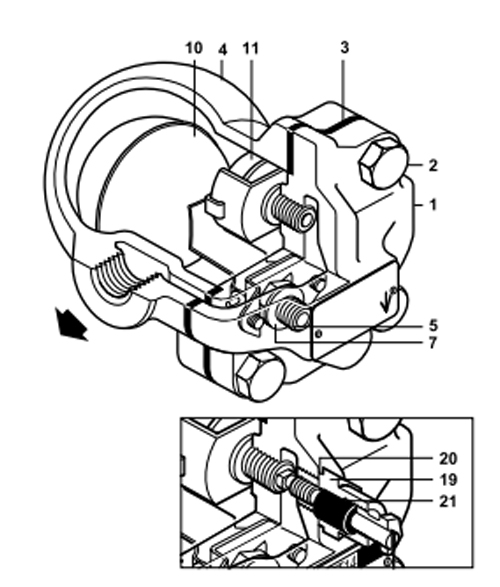
| 1. | Cover | Cast Iron | IS 210 FG 260 |
| 2. | Cover bolts. | Carbon Steel | H.T.IS1367, Gr8 |
| 3. | Cover gasket | Asbestos free synthetic fibre | - |
| 4. | Base | Cast Iron | IS 210 FG 260 |
| 5. | Main valve seat | Stainless Steel Type 304 | ASTM A743 Gr. CA40 |
| 6. | Main valve seat gasket | ||
| 7. | Main valve assembly screws | Stainless Steel Type 304 | IS-1364 |
| 8. | Ball float & lever | Stainless Steel Type 304 | ASTM A240 |
| 9. | Air vent element | Stainless Steel Type 316 | ASTM A240 |
| 10. | SLR unit | Stainless Steel Type 410 | ASTM A276 |
| 11. | SLR unit gasket | Stainless Steel Type 304 | ASTM A240 |
| 12. | Pivot frame type 304 | Stainless Steel | ASTM A240 |
| 13. | SLR Seal | Graphite | - |
| Size (DN) | A | B | C | D | E | F | Wt.(kg) |
|---|---|---|---|---|---|---|---|
| 15/20 (NIBR) | 121 | 107 | 67 | 147 | 105 | 30 | 2,5 |
| 15/20 (IBR) | 130 | 109 | 72 | 152 | 120 | 20 | 2.9 |
| 25 (IBR/NIBR) | 141 | 109 | 72 | 160 | 135 | 20 | 4.0 |
How to Fit - General
With suitable isolation, repairs can be carried out with the trap on line. When reassembling it is advisable to make sure that all joint faces are clean,
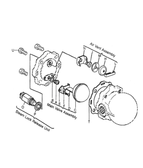
Remove cover bolts U and lift off cover
Remove complete float assembly by undoing the two screws D. Remove main valve seat A and replace with a new one supplied with a new gasket B.
Fit complete new float assembly by tightening the assembly set screws D.
Refit the cover using new gasket T.
Remove spring clip L, element H and spacer plate M. Unscrew seat, frame N assemble spacer plate, fit element and dip.
Align complete air vent horizontally so that the frame clears the cover
DN 15 Single Orifice Float Trap, SOFT31-T-4,5 bar g, TV, screwed BSPT
The parts available as spares are shown in heavy outline. Parts drawn in dotted line are not available as spares.
| Main valve assembly with Float | A, B,C,D, (2 OFF) E,F |
| Air Vent Assembly | H, J, L, M, N |
| Steam Lock Release Unit | OP |
| Cover Gasket (packet of 5) | T |
| Float | C |
| Screen (Packet of 5) | - |
Always order spares by using the description given in the column above and stating the size of the trap.
Example: Main valve assembly for DN 15 Single Orifice Float Trap SOFT31-T-4,5
| Part | - | Torque (Nm) |
| Main Valve Seat (A) | 18 mm A/F | 50/55 |
| Main Valve Assembly Screws (D) | - | 2.5/3 |
| Air Vent Seat (J) | 17 mm A/F | 50/55 |
| Steam Lock Release Seat (S) | 17mm A/F | 50/55 |
| Cover Bolts | 17 mm A/F | 40/55 |

