- M :- +91 966 423 0207
- E :- salimexport.in@gmail.com
-

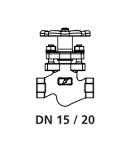
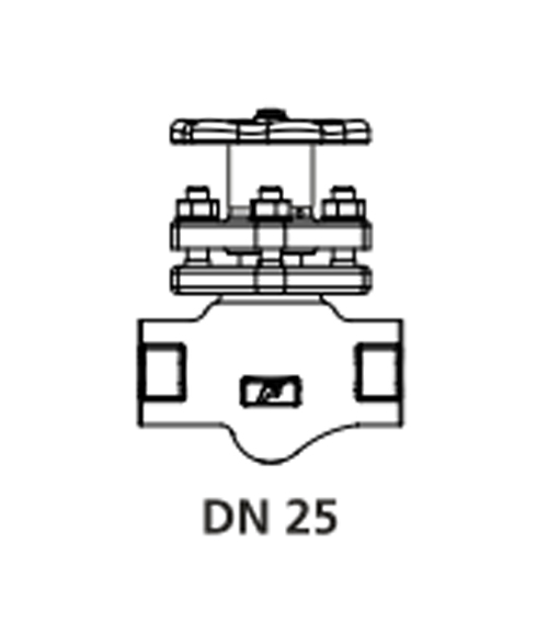
1.DN 15/20/25/32/40 Screwed BSPT/NPT, socket weld ends, flanged to class 150/300/600 available on special request
2. DN 50/65/80/100/125/150/200/250 Flanged to class 150/300
3. DN 50/65/80/100/125/150/200/250 Flanged to PN16/PN25/PN40
For higher sizes DN 250 and 300 contact Forbes Marshall
| For DN 15/20/25/32/40 Socket weld ends | |
|---|---|
| Maximum operating pressure | 78 bar g |
| Maximum operating temperature | 425 deg c |
| Maximum hydraulic test pressure | 156 bar g (IBR requirement) |
| For DN 15/20/25 Screwed ends | |
| Maximum operating pressure | 78 bar g |
| Maximum operating temperature | 425 deg c |
| Maximum hydraulic test pressure | 156 bar g (IBR requirement) |
| For DN 32/40 Screwed ends | |
| Maximum operating pressure | 41.5 bar g |
| Maximum operating temperature | 425 deg C |
| Maximum hydraulic test pressure | 83 bar g (IBR requirement). |
| Sr.No | Description | Material |
|---|---|---|
| 1 | Body | Forged Carbon Steel ASTM A105N |
| 2 | Bonnet | Forged Carbon Steel ASTM A105N |
| 3 | Piston | Stainless Steel ASTM A 276 TYPE 304 |
| 4 | Spindle | Stainless Steel ASTM A 276 TYPE 410 |
| 5 | Nyloc Nut | Carbon Steel |
| 6 | Stud | Carbon Steel ASTM A193 Gr. B7 |
| 7 | Nut | Carbon Steel ASTM A 194 Gr.2H |
| 8 | Belleville Washer | Spring Steel 50CrV4 |
| 9 | Sealing stack | S.S. Reinforced Graphite |
| 10 | Spacer | Stainless Steel ASTM A 276 TYPE 410 |
| 11 | *Handwheel | Sheet Metal / SG Iron |
| 12 | Gap rings | Stainless Steel 410 |
| 13 | Split Nut | Brass DIN En12164 |
| 14 | Thrust Plate | Stainless Steel ASTM A 275 TYPE 420 |
| *Note: For DN 15-25 Handwheel - Sheet Metal For DN32-40 Hand wheel-S.G. Iron | ||
| Maximum allowable pressure | 102 bar g @ 38 °C |
| Maximum operating pressure | 78 bar g @ 295 °C |
| Maximum operating temperature | 425 °C @ 57.5 bar g |
| Maximum hydraulic test pressure | 156 bar g |
| Size (DN) | A | B | C |
|---|---|---|---|
| 15 | 110 | 118 | 146 |
| 20 | 110 | 118 | 146 |
| 25 | 126 | 133 | 133 |
| 32 | 165 | 175 | 215 |
| 40 | 165 | 175 | 215 |
| Size (DN) | A* | C | B | ||
|---|---|---|---|---|---|
| Class 150 | Class 300 | Class 600 | |||
| 265 | 15 | 252 | 265 | 118 | 146 |
| 20 | 252 | 265 | 265 | 118 | 146 |
| 25 | 260 | 278 | 278 | 133 | 165 |
| 32 | 305 | 317 | 320 | 175 | 215 |
| 40 | 305 | 317 | 320 | 175 | 215 |


| Maximum allowable pressure | 16 bar g at 38 deg C |
| Maximum operating pressure | 16 bar g at 204 deg C |
| Maximum operating temperature | 425 deg C at 9.1 bar g |
| Cold hydraulic test pressure | 24 bar g |
| Maximum allowable pressure | 25 bar g at 38 deg C |
| Maximum operating pressure | 25 bar g at 226 deg C |
| Maximum operating temperature | 425 deg C at 14 bar g |
| Cold hydraulic test pressure | 38 bar g |
| Maximum allowable pressure | 40 bar g at 38 deg C |
| Maximum operating pressure | 39 bar g at 250 deg C |
| Maximum operating temperature | 425 deg C at 22.8 bar g |
| Cold hydraulic test pressure | 60 bar g |
| Maximum allowable pressure | 19,6 bar g at 38 deg C |
| Maximum operating pressure | 14 bar g at 197 deg C |
| Maximum operating temperature | 425 deg C at 5.5 bar g |
| Cold hydraulic test pressure | 28 bar g (IBR requirement) |
| Sr.No. | Description | Material |
|---|---|---|
| 1 | Body | Cast Steel ASTM A 216 Gr.WCB |
| 2 | Bonnet | Cast Steel ASTM A 216 Gr.WCB |
| 3 | Piston | Stainless Steel ASTM A 276 TYPE 304 |
| 4 | Spindle | Stainless Steel ASTM A 276 TYPE 410 |
| 5 | Nyloc Nut | Carbon Steel |
| 6 | Stud | Carbon Steel ASTM A193 Gr. B7 |
| 7 | Nut | Carbon Steel ASTM A 194 Gr.2H |
| 8 | Belleville Washer | Spring Steel 50CrV4 |
| 9 | Sealing stack | S/S Reinforced Graphite |
| 10 | Spacer | Stainless Steel ASTM A 743 Gr.CA15 |
| 11 | Handwheel | SG Iron |
| 12 | Thrust Plate | Stainless Steel ASTM A 276 TYPE 420 |
| 13 | Name Plate | Stainless Steel ASTM A 240 TYPE 304 |
| 14 | Split Nut | Brass DIN EN 12164 |
| 15 | Gap Rings | Stainless Steel SS 420 |
| Maximum allowable pressure | 51 bar g at 38 deg C |
| Maximum operating pressure | 41,5 bar g at 253 deg C |
| Maximum operating temperature | 425 deg C at 28,8 bar g |
| Cold hydraulic test pressure | 83 bar g (IBR requirement) |
| ANSI Class | L | D | PCD | H | No. of Holes | T | E | F | Approx Wt |
|---|---|---|---|---|---|---|---|---|---|
| 150 | 203 | 152 | 121 | 19 | 4 | 19 | 210 | 262 | 14.5 kg |
| 200 | 267 | 165 | 127 | 19 | 8 | 22 | 210 | 262 | 17.5 kg |
| PN 16 | 230 | 165 | 125 | 18 | 4 | 18 | 210 | 262 | 14.5 kg |
| PN 40 | 230 | 165 | 125 | 18 | 4 | 20 | 210 | 262 | 17.5 kg |
| Sr.No. | Description | Material |
| 1 | Body | Cast Steel ASTM A 216 Gr.WCB |
| 2 | Bonnet | Cast Steel ASTM A 216 Gr.WCB |
| 3 | Piston | Stainless Steel ASTM A 351 CF8 |
| 4 | Body sealing stack | S/S Reinforced Graphite |
| 5 | Spacer | Stainless Steel ASTM A 743 CA 15 |
| 6 | Spindle | Stainless Steel ASTM A 276 Type 410 |
| 7 | Stem | Stainless Steel ASTM A 276 Type 304 |
| 8 | Split Nut | Brass DIN EN 12164 |
| 9 | LH Nut | Stainless Steel ASTM A 276 Type 304 |
| 10 | Gland Sealing Stack | S/S Reinforced Graphite |
| 11 | Threaded Bush | Ph. Bronze |
| 12 | Back Seat | Stainless Steel ASTM A 276 Type 410 |
| 13 | Gland Nut | Stainless Steel ASTM A 194 Gr.2H |
| 14 | Bonnet Sealing Ring | Graphite |
| 15 | Stud | Carbon Steel ASTM A 193 Gr.B7 |
| 16 | Nut | Carbon Steel ASTM A 194 Gr.2H |
| 17 | Beleville Washer | Spring Steel 50CrV4 |
| 18 | Handwheel | S.G. Iron |
| 19 | Nyloc Nut | Carbon Steel |
| 20 | Washer | ASTM A 240 TYPE 304 Stainless Steel |
| 21 | Name Plate | Stainless Steel ASTM A 240 TYPE 304 |
| 22 | Thrust Plate | Stainless Steel ASTM A 276 TYPE 420 |
| 23 | Gap Rings | Stainless Steel SS420 |
| Sizes (DN) | Pressure Class | L | D | PCD | H | NO. OF Holes | T | E | F | Approx. Weight (Kg) | |
|---|---|---|---|---|---|---|---|---|---|---|---|
| 65 | CLASS 300 | 292 | 191 | 149 | 22 | 8 | 25 | 335 | 400 | 31 | |
| 65 | CLASS 150 | 216 | 178 | 140 | 19 | 4 | 22 | 335 | 400 | 27 | |
| 65 | PN 16/25 | 290 | 185 | 145 | 18 | 8 | 18 | 335 | 400 | 27 | |
| 65 | PN40 | 290 | 185 | 145 | 18 | 8 | 22 | 335 | 400 | 31 | |
| 80 | CLASS 300 | 318 | 210 | 168 | 22 | 8 | 28 | 320 | 384 | 37 | |
| 80 | CLASS 150 | 241 | 191 | 152 | 19 | 4 | 24 | 320 | 384 | 31 | |
| 80 | PN 16/25 | 310 | 200 | 160 | 18 | 8 | 24 | 320 | 384 | 31 | |
| 80 | PN 40 | 310 | 200 | 168 | 18 | 8 | 20 | 320 | 479 | 37 | |
| 100 | CLASS 300 | 356 | 254 | 200 | 22 | 8 | 32 | 395 | 479 | 58 | |
| 100 | CLASS 150 | 292 | 229 | 191 | 19 | 8 | 24 | 395 | 479 | 47 | |
| 100 | PN 16/25 | 350 | 220 | 180 | 20 | 8 | 18 | 395 | 479 | 47 | |
| 100 | PN 40 | 350 | 235 | 190 | 24 | 8 | 22 | 395 | 479 | 58 | |
| 125 | CLASS 300 | 400 | 280 | 235 | 24 | 8 | 35 | 446 | 540 | 87 | |
| 125 | CLASS 150 | 356 | 254 | 216 | 22 | 8 | 24 | 446 | 540 | 70 | |
| 125 | PN 16/25 | 400 | 250 | 210 | 18 | 8 | 22 | 446 | 540 | 70 | |
| 125 | PN 40 | 400 | 270 | 220 | 26 | 8 | 26 | 446 | 540 | 87 | |
| 150 | CLASS 300 | 445 | 318 | 270 | 22 | 12 | 37 | 486 | 598 | 117 | |
| 150 | CLASS 150 | 406 | 279 | 241 | 22 | 8 | 26 | 486 | 598 | 90 | |
| 150 | PN 16/25 | 480 | 285 | 240 | 22 | 8 | 22 | 486 | 598 | 90 | |
| 150 | PN 40 | 480 | 300 | 250 | 26 | 8 | 28 | 486 | 598 | 117 | |
| 200 | CLASS 300 | 559 | 381 | 330 | 25 | 12 | 41 | 591 | 728 | 210 | |
| 200 | CLASS 150 | 495 | 343 | 298 | 22 | 8 | 28 | 591 | 728 | 164 | |
| 200 | PN 16/25 | 600 | 340 | 295 | 22 | 12 | 24 | 591 | 728 | 164 | |
| 200 | PN 40 | 600 | 375 | 320 | 30 | 12 | 34 | 591 | 728 | 210 | |
| 250 | CLASS 300 | 622 | 455 | 381 | 26 | 16 | 48 | 653 | 813 | 340 | |
| 250 | CLASS 150 | 622 | 405 | 362 | 25 | 12 | 31 | 653 | 813 | 300 | |
| *250 | PN 16/25 | 730 | 405 | 355 | 26 | 12 | 26 | 653 | 813 | 340 | |
| *250 | PN 40 | 730 | 450 | 385 | 33 | 12 | 38 | 653 | 813 | 370 | |
| *For DN250 Class PN16/25 and PN40, please contact Forbes Marshall | |||||||||||
The valve is designed for installation in a vertical or horizontal line with inlet as per the arrow direction. To open the valve turn hand wheel till it stops at the top and to close, turn hand wheel till it touches the bonnet. Do not use "F" key. If any leakage is observed during operation at the outlet, close valve fully and tighten opposite nuts equally half or one turn until leakage stops.
Pressure: Before attempting any maintenance of the valve, ensure that pressure is isolated and safely vented to atmosphere. Do not assume that the system is depressurized even when a pressure gauge indicates zero.
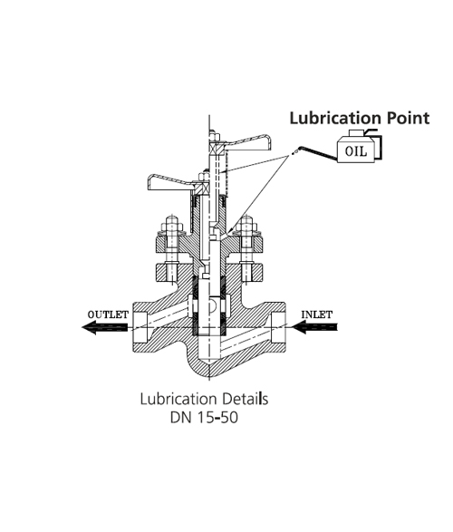
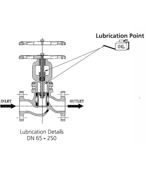
Use Molykote M30 oil for lubrication. For DN 15-50 sizes lubricate spindle regularly through bonnet hole and spindle threads. For DN 65-250 lubricate frequently through spindle threads, split nut and stem.
Order spares as per the code no. specified in the user manual.
| Sr. No. | Size (DN) | Torque (Nm) |
|---|---|---|
| 1 | 15 | 3-5 |
| 2 | 20 | |
| 3 | 25 | 5-7 |
| 4 | 32 | |
| 5 | 40 | 18-20 |
| 6 | 50 | |
| 7 | 65 | 20-25 |
| 7 | 65 | |
| 8 | 80 | 50-60 |
| 10 | 125 | |
| 11 | 150 | 70-80 |
| 12 | 200 | |
| 13 | 250 | 80-90 |
| Sr. No. | Size (DN) | Torque (Nm) |
|---|---|---|
| 1 | 65 | 35-45 |
| 2 | 80 | 35-45 |
| 3 | 100 | 75-85 |
| 4 | 125 | 75-85 |
| 5 | 150 | 85-95 |
| 6 | 200 | 95-110 |
| 7 | 250 | 95-110 |
| DN 15-50 | Sealing stacks |
| DN 65-250 | Body sealing stack set, bonnet sealing ring and gland sealing stack |
| Size (DN) | 15 | 20 | 25 | 32 | 40 | 50 | 65 | 80 | 100 | 125 | 150 | 200 | 250 |
|---|---|---|---|---|---|---|---|---|---|---|---|---|---|
| Kv | 2.5 | 2.5 | 5.8 | 13 | 13 | 41 | 51 | 77 | 131 | 194 | 221 | 438 | 675 |

